What Is a Custom Gear Motor and How Does It Work?

Time:2026-09-22 Author:Amelia
0%

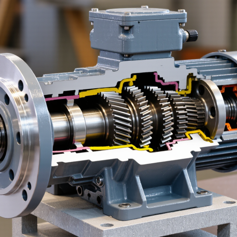
A Custom Gear Motor combines an electric motor with a tailored gear system. It delivers controlled torque, speed, and movement for a specific machine. Unlike an off-the-shelf unit, its dimensions, gear ratio, shaft design, mounting pattern, and electrical features can match the application.

Mechanical-design authority Robert L. Mott states, “The purpose of a gear train is to transmit motion and power from one rotating shaft to another.” This principle explains the basic operation. The motor creates rotational force. The gears then reduce speed or increase torque. For example, a small motor may turn quickly, while the output shaft moves slowly enough to lift a conveyor load. The gear teeth transfer force through precise contact. Lubrication helps reduce friction and wear.

Designing one is not simply a matter of adding stronger gears. Engineers must examine load cycles, startup torque, noise, heat, alignment, and available space. A housing only a few millimeters too large may prevent installation. An unsuitable gear ratio may cause overheating. That detail is easy to underestimate.

A Custom Gear Motor can improve reliability, but it is not automatically the best choice. Poor measurements, unclear duty requirements, or unrealistic cost targets can weaken the result. Testing under real operating conditions remains essential. Sometimes, the first design is only a useful lesson. This guide examines how these motors work, why customization matters, and which practical decisions influence performance.
What Is a Custom Gear Motor and How Does It Work?

What a Custom Gear Motor Is and What Makes It Different

A custom gear motor is an integrated drive unit designed for a specific machine, not a standard motor with a random gearbox attached. Its motor produces rotation, while the gearbox adjusts speed and torque through meshing gears. This combination can fit unusual space, load, and control requirements.

The difference appears in the details. A designer may specify a 24-volt motor, a 35:1 reduction ratio, and an output shaft with a particular length. Mounting holes can match a compact conveyor frame. The housing may also include sealing for dust, moisture, or frequent cleaning. In practice, engineers examine starting torque, duty cycle, operating temperature, noise, and expected service life before selecting gear teeth and bearings.

Testing makes the design more reliable. A prototype might drive a loaded roller for several hours while technicians measure current, vibration, and housing temperature. Small changes matter. A different lubricant can reduce heat, while a stronger bearing can prevent early shaft movement. The first calculation is rarely perfect. Real loads often vary more than a spreadsheet suggests.

Custom work can improve efficiency and simplify installation, but it requires accurate information. An underestimated load may cause overheating or gear wear. A poorly chosen ratio may create slow movement without enough force. Engineers should verify these assumptions through testing, maintenance records, and clear operating limits. That practical feedback is what makes a custom gear motor genuinely different.

The Main Components and Their Roles in a Custom Gear Motor

A custom gear motor combines an electric motor with a gear train designed for a specific machine. The motor’s stator creates a magnetic field, while the rotor converts electrical energy into rotation. This rotation reaches the gear train through the motor shaft. Gears then reduce speed and increase torque at the output shaft. The result is controlled movement, such as turning a conveyor roller or positioning a valve.

The main components must work as one system. Bearings support rotating shafts and limit friction. The housing protects internal parts and helps manage vibration. Gears determine the speed ratio, torque capacity, and direction of rotation. Lubricant reduces tooth wear, while seals help keep dust and moisture away. Some custom units also include encoders, brakes, or temperature sensors. During practical design work, engineers check load, starting torque, duty cycle, available space, and heat. A motor can meet the torque target yet still overheat in continuous service. That detail is easy to miss.

Tips: Measure the real load, not just the rated load. Check shaft alignment carefully. Leave room for cooling and maintenance. Choose materials according to noise, wear, and operating temperature. Test the motor under actual working conditions. A quiet prototype may behave differently after hours of operation. That is where design assumptions need another review.

How Motor Power Becomes Controlled Mechanical Motion

What Is a Custom Gear Motor and How Does It Work?

A custom gear motor combines an electric motor with a purpose-built gearbox. The motor creates rotation from electrical power. The gearbox then controls that rotation for a specific mechanical task. Its gears can reduce speed and increase torque, helping a small motor move a heavier load. This controlled output may turn a conveyor, adjust a valve, or position a compact mechanism.

Engineers select the gear ratio, shaft size, housing, and mounting pattern around the real application. A higher reduction ratio produces slower movement but stronger turning force. A lower ratio allows faster movement with less torque.

During testing, technicians measure current, vibration, heat, noise, and output speed. These details reveal whether the motor performs reliably under changing loads. In practice, calculations are rarely perfect. Friction, alignment, and sudden resistance can change the expected result.

Tips: Define the load, speed, duty cycle, and available space before choosing a gear motor. Leave a safety margin for startup torque. Check shaft alignment carefully. Even a small offset can create extra heat and wear. If motion must stop precisely, consider feedback from an encoder or position sensor. It adds complexity, but it can improve repeatability. A thoughtful design also allows access for inspection and lubrication. That small decision often saves time later.

How Custom Gear Motors Are Designed for Specific Applications

What Is a Custom Gear Motor and How Does It Work?

A custom gear motor combines an electric motor with a purpose-built gearbox. The motor supplies rotational energy. The gearbox reduces speed and increases usable torque. Designers select gear ratios, materials, bearings, seals, and mounting features for one application. According to the International Energy Agency, electric motor systems consume roughly half of global electricity. Small efficiency gains can therefore matter across thousands of operating hours.

Design Begins With Real Operating Conditions Design begins with real operating conditions, not a catalog speed. Engineers measure required torque, output speed, duty cycle, starting load, and available space. A conveyor may need steady torque and low noise. A medical mechanism may require compact dimensions, low backlash, and controlled movement. Outdoor equipment needs corrosion resistance and sealing. IEC 60034-30-1 efficiency classifications help compare motor performance, while thermal testing confirms whether heat can escape from the housing.

Why the Gearbox Matters The gearbox is often the difficult part. Helical gears can improve efficiency, while planetary arrangements provide high torque in a compact package. Engineers also check shaft loads, lubrication life, vibration, and emergency stops. The U.S. Department of Energy reports that motor-driven systems represent a major share of industrial electricity use, making losses worth examining carefully. Yet a neat calculation can still miss field realities. Dust, misalignment, and frequent starts may shorten service life. Good design uses testing, operator experience, and revision. Not every first prototype is right.

Key Factors for Selecting and Evaluating a Custom Gear Motor

What Is a Custom Gear Motor and How Does It Work?

A custom gear motor combines an electric motor with a gearbox designed for a specific machine. The motor creates rotation. The gears reduce speed and increase usable torque. Engineers can adjust gear ratio, shaft position, voltage, mounting, sealing, and braking. This matters when standard units create noise, heat, or alignment problems.

Key Factors for Selecting and Evaluating a Custom Gear Motor

Start with the real load, not an estimated load. Record torque, speed, duty cycle, starts per hour, and available space. A conveyor moving heavy cartons needs different gearing from a compact medical actuator. The U.S. Department of Energy reports that motor-driven systems can consume more than half of industrial electricity. Efficiency deserves attention. However, efficiency figures can mislead when testing conditions differ. Compare values at the same load, speed, voltage, and temperature. The International Energy Agency also identifies efficient motor systems as an important industrial energy-saving opportunity.

Tip: Ask for a complete performance curve.

Check peak torque, continuous torque, backlash, thermal rise, ingress protection, and expected service life. Material choice matters too. Hardened gears may support demanding cycles, while quieter materials can reduce workplace noise. Confirm whether the gearbox can survive shock loads. A calculation may look correct, yet field vibration can expose weak assumptions. Request prototype testing under actual duty conditions. Include cable routing and maintenance access early. These details are often ignored. They should not be. Industry market reports can guide trends, but your machine data should control the final specification.

What Is a Custom Gear Motor and How Does It Work?

A custom gear motor combines an electric motor with a gearbox to convert motor speed into usable output speed and torque. The chart compares calculated output speed and torque for a 0.25 kW motor running at 1,500 rpm across several gear ratios. Output torque is estimated from mechanical power after typical gearbox efficiency losses.

When selecting a custom gear motor, evaluate the required output speed, continuous and peak torque, duty cycle, gearbox efficiency, allowable backlash, thermal limits, mounting constraints, and environmental protection requirements.

FAQS

What is a custom gear motor?

It combines an electric motor with a gearbox designed for one mechanical task. The motor creates rotation. The gearbox controls speed and torque. It may drive a conveyor, valve, or positioning mechanism.

How does the gearbox change motor performance?

A higher reduction ratio lowers output speed and increases turning force. A lower ratio provides faster movement with less torque. This trade-off is easy to underestimate.

What information is needed before selecting one?

Record the load, required torque, output speed, duty cycle, starts per hour, and available space. Also check voltage, shaft size, mounting pattern, and operating temperature. Guesswork can become expensive.

Why is shaft alignment important?

Even a small offset can increase heat, vibration, and gear wear. Inspect the coupling and shaft position during installation. A smooth test run may still hide a gradual alignment problem.

How can a custom gear motor improve energy performance?

Correct sizing reduces unnecessary electrical losses during long operating hours. Compare efficiency at the same load, speed, voltage, and temperature. One published number is not enough.

What should testing include?

Test current, vibration, temperature, noise, output speed, and torque. Use the machine’s real duty cycle when possible. Dust, shock loads, and frequent starts can change the result.

When is an encoder or position sensor useful?

It helps a mechanism stop at a repeatable position. This suits compact actuators, valves, and indexing equipment. Feedback improves control but adds wiring, cost, and failure points.

What design details are often overlooked?

Leave access for inspection, lubrication, cable routing, and future adjustment. Confirm sealing against moisture or dust when needed. The neatest housing may be difficult to service. That mistake happens.

Conclusion

A Custom Gear Motor is an integrated drive system designed to deliver controlled mechanical motion for a specific operating requirement. Unlike a standard motor and gearbox combination, it is developed as a coordinated unit, with the motor, gears, shafts, bearings, housing, and control features selected to work together. The motor produces rotational power, while the gearbox adjusts speed, torque, and direction so the output matches the needs of the equipment.

Designing a Custom Gear Motor begins with understanding the application, including load, speed, duty cycle, available space, noise limits, environmental conditions, and expected service life. Engineers can then determine the appropriate motor rating, gear ratio, materials, mounting style, and protection level. When selecting and evaluating a unit, users should consider efficiency, starting torque, thermal performance, reliability, maintenance requirements, and total operating cost. A well-matched design improves motion control, reduces unnecessary energy use, and provides dependable performance in its intended application.

Amelia

Amelia

Amelia is a seasoned marketing professional with a wealth of expertise in our company’s core offerings. With an unwavering passion for driving growth and innovation, she plays a pivotal role in shaping our marketing strategies and enhancing brand visibility. A key aspect of her responsibilities......