1 / 5
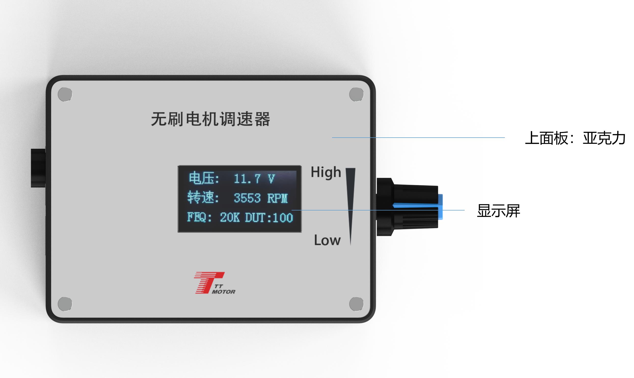
- The output signal changes of the three interfaces (7 to 9) are adjusted by the potentiometer.
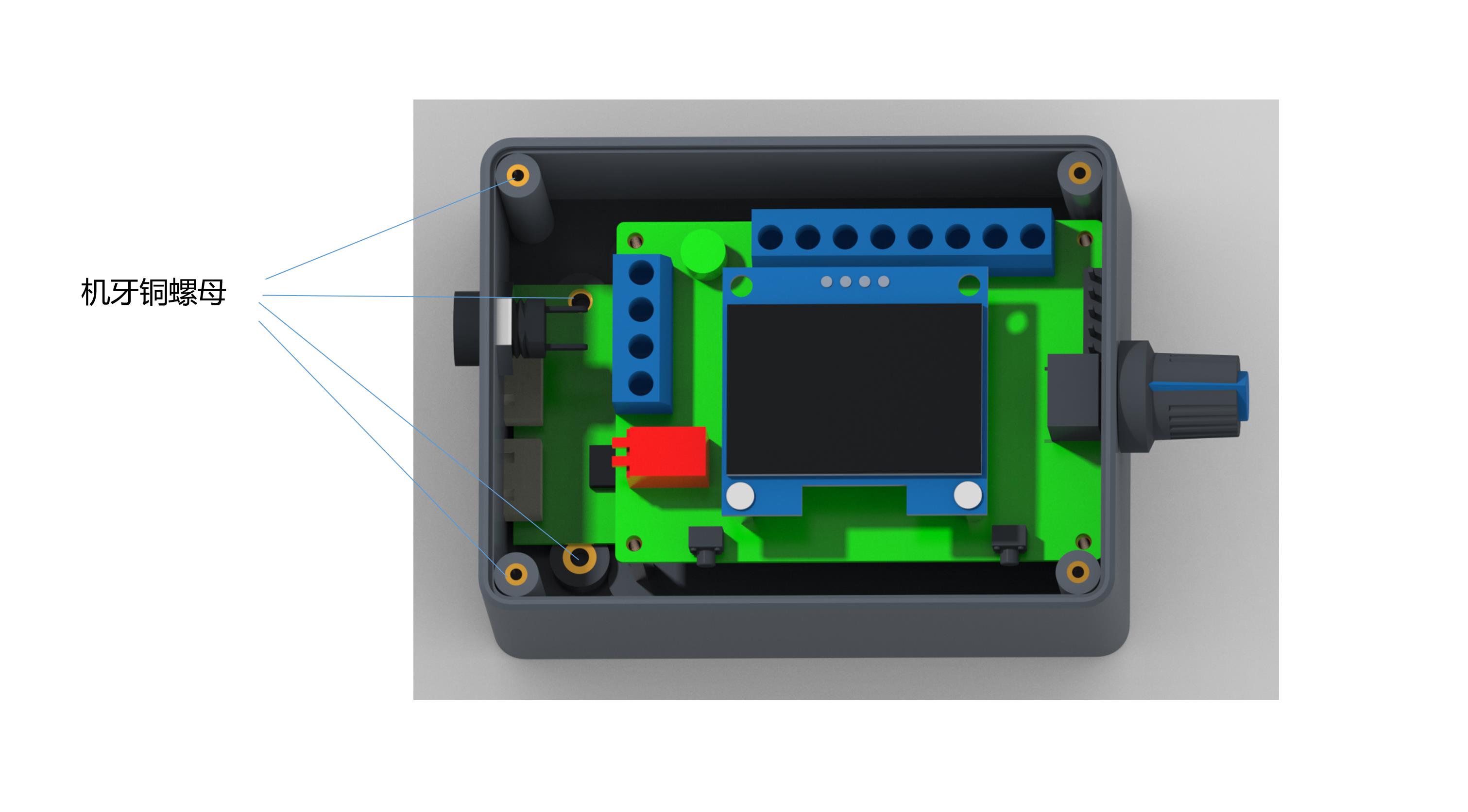
- FG/FG*3 Setting: Choose based on actual motor feedback requirements. Without a jumper cap, it operates as a single FG signal; adding the jumper cap changes it to 3 times FG (FG*3). The same setting rule applies to CW/CCW.
Before powering on, press and hold touch switch 1. Turn on the power and release the switch when "FEQ:20K" appears. Press switch 1 to decrease and switch 2 to increase the frequency. Adjustable to the required frequency; factory default is 20KHz.
Before powering on, hold down touch switch 1 and touch switch 2 simultaneously. Turn on the power and release both buttons when "number of poles: 1 polarity" displays. Press touch switch 1 to decrease and touch switch 2 to increase. Adjust to the motor's designed pole number; factory default is 1 pole.
The FG/FG*3 pin (indicated in Figure 1) sets the feedback multiplier. Adjust according to whether the motor requires single FG or 3 times FG feedback: add a jumper cap for 3 times FG, or leave it without a jumper cap for single FG.
The CW/CCW pin (indicated in Figure 1) configures the initial state of motor direction. Set this based on the motor's default rotation (CW or CCW) when the direction line is suspended. Add a jumper cap for CCW, or leave it off for CW.
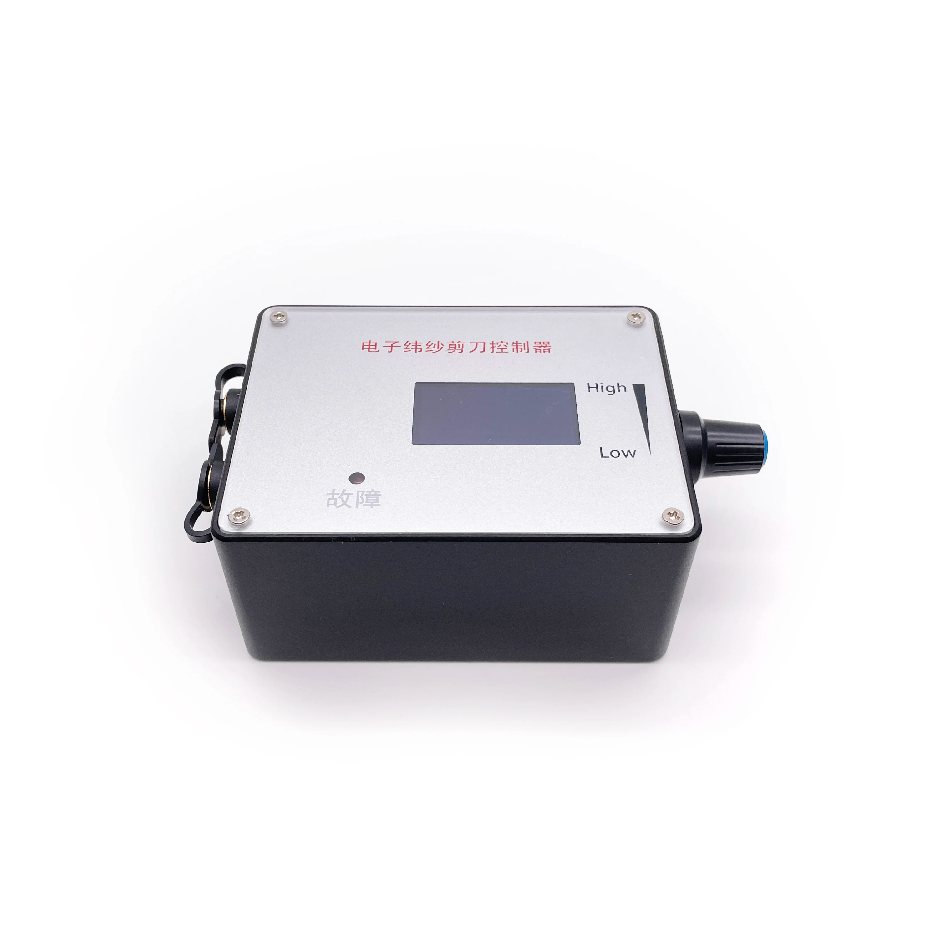
The governor operates within a DC 5V-28V voltage range with a maximum rated current of 2A. If you need to control a motor requiring more current, the motor's power line must connect directly to the power supply rather than passing through the governor.
Hold down touch switch 1 before powering on, then turn on the power. Release the button when the screen displays "FEQ:20K". You can then press switch 1 to decrease or switch 2 to increase the frequency. The factory default setting is 20KHz.
Press and hold both touch switches 1 and 2 before powering on. Turn on the power and release the switches when the screen shows "number of poles: 1 polarity". Use touch switch 1 to decrease and touch switch 2 to increase the pole count. The factory default is 1 pole.
The jumper cap on the FG/FG*3 pin sets the feedback multiplier. If no jumper cap is added, the feedback operates as a single times FG. If the jumper cap is added, it switches to 3 times FG (FG*3). Adjust this based on your motor's feedback requirements.
The positive and negative inputs must be connected strictly according to the wiring instructions. Reversing the polarity will cause the governor to stop functioning and will burn the internal components of the board.
The five control ports (numbered 5 to 9) are designed for low-voltage signals. You must ensure that the voltage accessed on these ports does not exceed 5V to prevent damage.