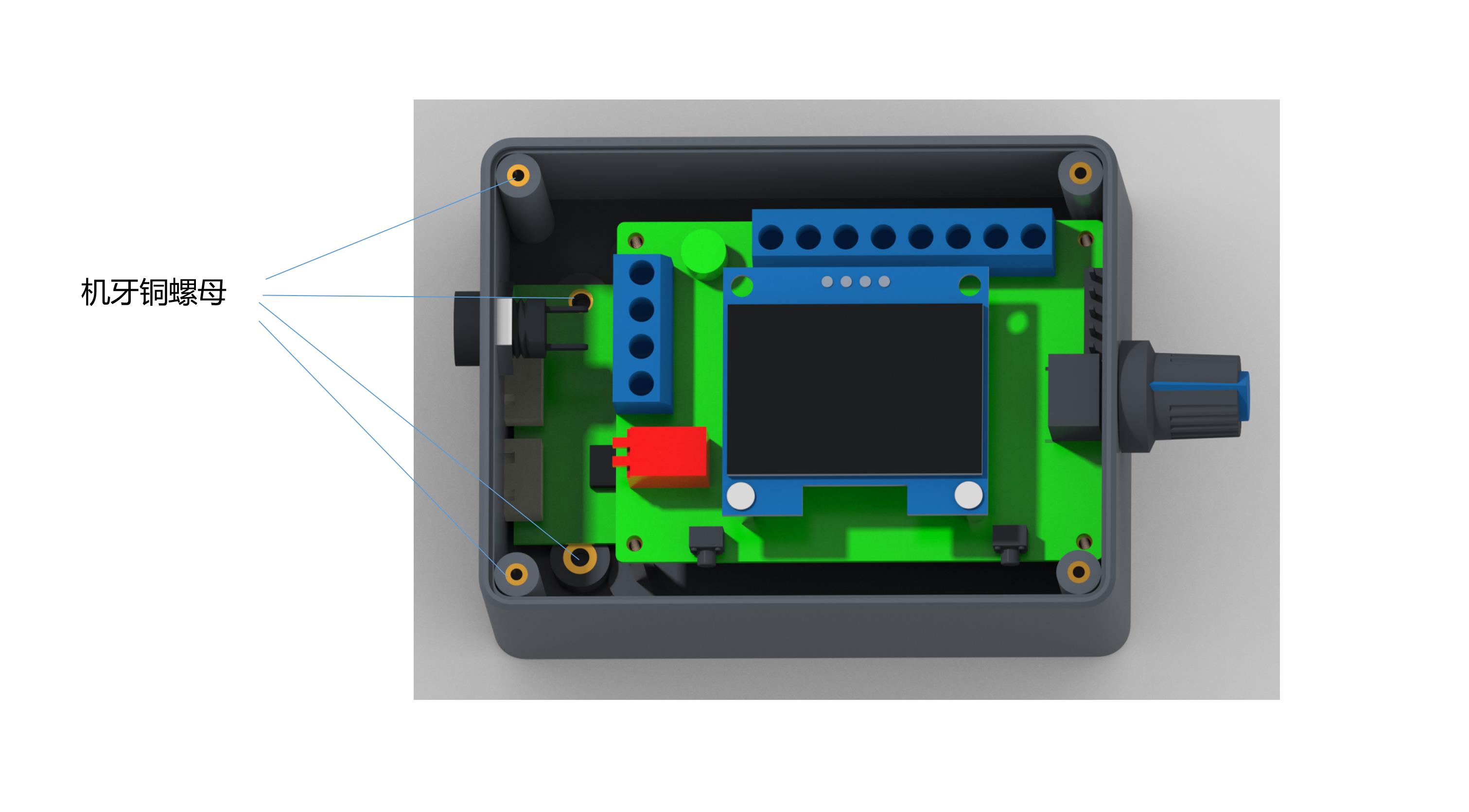
1Governor, motor power supply positive input.
2Governor, motor power input negative.
3The positive output of the power supply of the motor.
4Negative output of the power supply of the motor.
5High and low level output of positive and negative rotation control. High level 5V, low level 0V. Controlled by touch switch 2 (F/R), the default is high level.
6High and low level output of brake control. High level 5V, low level 0V. Controlled by touch switch 1 (BRA), power on defaults to high level.
7Analog voltage output (0~5V). This interface is suitable for accepting analog voltage speed regulation motor.
8PWM1 reverse output. This interface is suitable for the motor that accepts PWM speed regulation, and the speed is inversely proportional to the duty cycle.
9PWM2 forward output. This interface is suitable for motors that accept PWM speed regulation, the speed is proportional to the duty cycle.